FAQ
We look forward to supporting you during the design-in phase with our FAQ, our extensive data package, and personal by phone or e-mail. If you can't find a suitable answer in the following FAQ, you are always welcome to contact our application support.
Email: applicationsupport@rrc-ps.com
Getting Started
When a battery is delivered to the customer, it is in "shipping mode". In this mode, the battery outputs 0 V and does not shows any LEDs. To wake the battery (exit shipping mode), apply maximum charging voltage to the battery. Wait 10 seconds before establishing communication with the smart battery and make sure no other devices are communicating on the bus.
NOTE: The RRC3570 will not output any voltage unless the "SYSTEM PRESENT"-pin ("T") is pulled to (S)GND.
Keywords: no LED, no light, no voltage, no current, doesn't work, storage
We strongly recommend using a smart charger with SMBus communication.
The smart battery sends information about Charging Voltage and Charging Current. These parameters depend on battery type, temperature, and age of the battery. Without a smart charger, you risk charging the battery wrong, which may lead from increased aging to triggering its internal protective circuits.
Keyword: I2C
RRC smart batteries can be used safely without establishing communication between the battery and the host.
However, it can be advantageous to exchange status information such as RelativeStateOfCharge(), RunTimeToEmpty() or BatteryStatus().
Keyword: I2C
Generally, during start-up, input capacitors in the connected application may be discharged.
The inrush current can be high because these capacitors need to be charged.
The current is highest during the first few microseconds, when the capacitors behave like a very low impedance load.
In many applications, no dedicated start-up current limiter is required.
However, inrush current should be evaluated in the following cases:
Case 1: Battery protection may be triggered.
If the inrush current is high enough or lasts long enough, the battery protection system may interpret it as an overload or short-circuit condition and switch off the battery.
Case 2: Components in the application may be overstressed.
Even if the battery does not switch off, the inrush current may stress components in the main power path, such as resistors, diodes, FETs, ferrites, connectors, relays, switches or fuses.
The system designer must verify that these components can withstand the expected start-up current and pulse energy.
Current limiting circuit
A simple way to reduce inrush current is to use a current-limiting circuit with a resistor in series with the application.
During start-up, the input capacitors are charged through the resistor, which limits the inrush current.
After a defined time or after reaching a defined voltage level, the resistor is bypassed by a switch, preferably a FET, to allow normal load current.
Depending on the system architecture, an NFET can be used in the ground path or a PFET in the positive path.
The bypass switch may be controlled by an MCU or by an analog delay circuit, for example using an RC filter.
Resistor selection
The resistor must be selected according to the expected inrush current, peak power and pulse energy during capacitor charging.
In addition to the resistance value, the permitted single-pulse load from the resistor datasheet must be checked. Depending on the input capacitance, battery voltage and start-up behavior, the required resistor size or type may vary.
Recommendation
We recommend validating the start-up behavior under worst-case conditions, including maximum battery voltage, discharged input capacitors, temperature effects and repeated start-up events.
The selected current-limiting circuit and resistor must be suitable for the specific application.
Setting Up Communication
As listed in the smart battery specification, the smart battery 7-bit address is 0b0001011.
I²C and SMBus look very much alike but are not the same. Some differences:
- Pull up resistors in the range of 10 to 15 kOhm for 3V3 systems and 15 kOhm for 5V systems.
- Clock speed 10 to 100 kHz
- Multi-masterFor more details, have a look at:
- General information: https://pdfserv.maximintegrated.com/en/an/AN476.pdf
- Physical layer specification: http://smbus.org/specs/smbus110.pdf
- Protocol layer specification: http://sbs-forum.org/specs/Keywords: I2C, pullup, pull-up
You can switch off the ChargingCurrent() and ChargingVoltage() broadcasts by writing into register BatteryMode() (address 0x03) and setting flag “ChargerMode” (Bit 14) to 1.
Equally, you can switch off the AlarmWarning() broadcast by writing into register BatteryMode() (address 0x03) and setting flag "AlarmWarning" (Bit 13) to 1.
Please note that after the battery is reset (e. g., after waking up from shipping mode or a deep-discharged state), these flags are also reset, and the broadcasts begin anew.
Keyword: messages
Running System – General Questions
The PCM is composed of three independent safety levels:
- 1st level protection: MOSFETs protect the battery cells against
- over-voltage,
- over-current,
- over-temperature,
- short circuit and
- under-voltage.
- 2nd level protection: A fuse is actively triggered
- if an over-current or over-voltage situation occurs, which has not been interrupted by the 1st level protection.
- if the 1st level protection fails to switch off the charge or discharge FET.
- if a voltage imbalance beyond predefined limits is recognized.
- 3rd level, cell-level protection: If both 1st and 2nd level protection failed to trigger and the cell's internal pressure considerably increases, resulting gases escape via an intended breaking point (known as venting) that cuts open the internal electrical path of the cell.
Keywords: BMS, battery management circuit, emergency, blow
- 1st level protection: MOSFETs protect the battery cells against
The T pin is a thermistor pin used to measure the temperature within the battery. But for smart batteries, instead of a thermistor, there is a fixed 300 Ω resistor. The smart battery only communicates its temperature via SMBus.
Now, when the battery is in shipping or shutdown mode, it outputs 0 V and does not communicate. The charger checks whether it sees the 300 Ω resistor at the T pin to recognize the battery. It then applies a wake-up charge as defined in the smart battery specification. The battery wakes-up and the charging process starts as normal.
Keywords: thermistor, resistance, ptc, ntc
We do not recommend trying to predict the State of Charge by the battery voltage. The results won't be reliable at all.
However, the fuel gauge inside a smart battery uses charge counters and a complex algorithm to correctly predict the SOC.
Standard batteries have a MaxError() register, which indicates the maximum error to expect from the fuel gauge IC. This register typically shows 1% and increases 0,05% after every 24h or after one full discharge cycle. If MaxError() reaches 5%, the battery requests a calibration cycle to recover its full accuracy. Once the calibration cycle is done, the MaxError() register resets to 1%.
Most often however, MaxError() resets to 1% automatically by normally charging and discharging the battery.
This happens if the following conditions are met:
Battery rests still for at least 5h after charging;
Battery discharges more than 37% State of Charge;
Battery rests still for at least 5h after discharging;
Ambient temperature is between 10°C and 40°C.
These conditions often naturally happen by normally using the battery, at least once every 2-3 months.
Thus, a calibration cycle generally is not needed.
Keywords: conditioning, correct, SOC
A calibration cycle is required to restore the accuracy of the FG (e.g. Full charge capacity or SOC).
The following procedure should be followed if a conditioning cycle is required.
Fully charge the smart battery
Stop charging
Let the smart battery rest still for five hours
Discharge the smart battery below 10% RSOC with a discharge current lower than 0.5C
Disconnect the smart battery from the load
Let the smart battery rest still for five hours. After this, the battery is calibrated and MaxError() register is reset to 1%.
It is necessary to perform the calibration cycle in at room temperature (approx. 25°C).
Keyword: calibrate
Charging - Trouble Shooting
The figure below shows that the charging process for Li-ion cells is split into two stages: the constant current phase (CC) and the constant voltage phase (CV). With a fully discharged battery, the CC phase is the first to take place. In this phase, the battery is charged by a constant current. Gradually, the voltage rises until it reaches the maximum charging voltage. Then the CV phase begins, in which the charging occurs at a fixed voltage. The charging current gradually decreases. When the charge current reaches a threshold called the "taper current", the battery is considered fully charged.
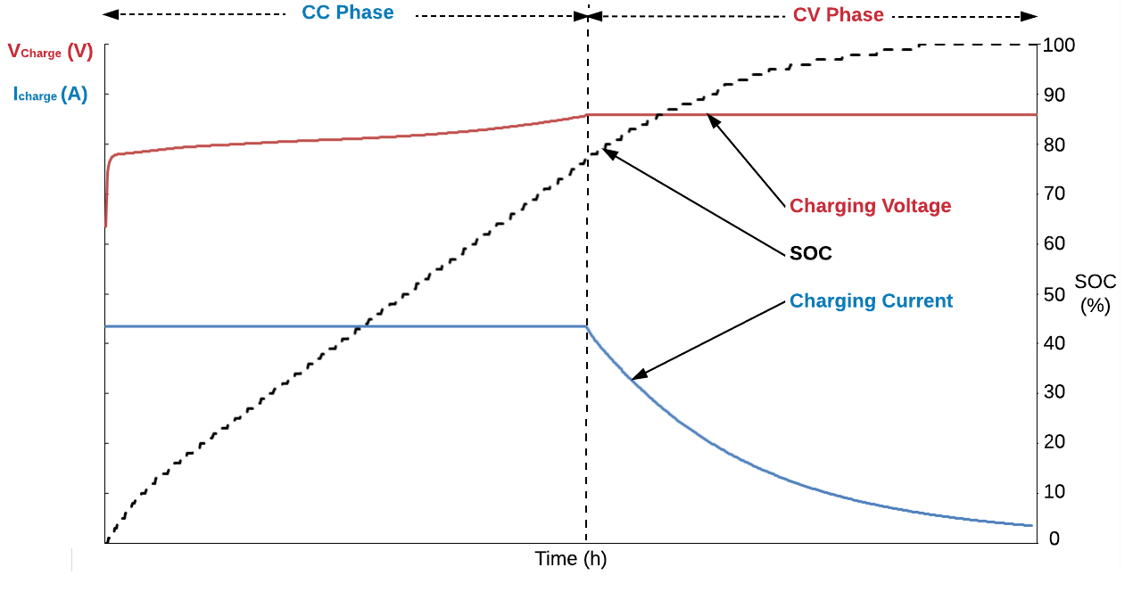
Li-ion Cell Charging Profile
A smart charger either "listens" to the battery broadcasts of ChargingCurrent() and ChargingVoltage() parameters, or actively polls these registers. Both parameters are dynamically updated according to the JEITA profile, which optimizes the charging process of Li-ion batteries. The smart charger then applies the requested charging current and voltage to the battery terminals.
Yes. All RRC standard smart batteries support JEITA profiles. They serve to adapt ChargingCurrent() and ChargingVoltage() as a function of temperature and battery health.
A "Level 2" smart charger acts as an SMBus slave device only. It adjusts its output in direct response to ChargingVoltage() and ChargingCurrent () broadcasts sent by the smart battery. In Level 2 charging, the Smart Battery is completely responsible for initiating the communication and for providing the charging algorithm to the charger.
In contrast, a "Level 3" smart charger can act as an SMBus master device. Thus, the battery does not necessarily need to broadcast its charging parameters. The Level 3 Smart Battery Charger can also poll the Smart Battery to determine the charging voltage and current the battery desires, and then dynamically adjust its output to meet its charging requirements.
A Level 3 Smart Battery Charger is free to implement an alternative specialized charging algorithm. It may also interrogate the Smart Battery for any other relevant data, such as time remaining to full charge, battery temperature or other data used to control proper charging or discharge conditioning. For example, a medical device with stricter temperature limits than the Smart Battery's self-contained charging algorithm may use a Level 3 Smart Battery Charger that factors the battery's reported temperature into its charging algorithm.
Packet Error Check (PEC) is an additional byte in the SMBus protocols used to check for an SMBus transmission error. Thus, it improves the communication reliability and robustness between the smart battery and the host/charger. If a charger level 2 is used paired with a battery that uses PEC in its broadcast, the charger must be PEC compliant.
The smart batteries which use PEC are: RRC2020; RRC2024; RRC2040; RRC 2040-2; RRC2054; RRC2057.
Coupling Multiple Smart Batteries
As listed in the smart battery specification, the smart battery 7-bit address is 0b0001011. This is valid for all smart batteries. If you consider using more than one battery in your system, view question 5.2.
Keywords: communicate, communication, several, parallel, serial, series, two, 2
Since all smart batteries have the same SMBus address, it is necessary to use a 1-to-2 DEMUX (e.g., PCA9544A) to ensure independent communication with only one battery.
Keywords: communicate, several, parallel, serial, series
Smart Battery Qualification
RRC batteries have a shelf life of 12 months under the following conditions:
- The battery is in shipping mode
- Ambient temperature is 25°C
- Initial SOC is 30% at 25°C.
To prevent the batteries from becoming deeply discharged, the user must recharge them to 30% SOC at least every 12 months. If the temperature is higher than 25°C, it may be necessary to recharge more often.
Keyword: storage
One cycle count corresponds to an accumulated discharge of 90% of design capacity.
Please refer to the respective smart battery specification or the battery label to access the list of certificates that each smart battery has. This table shows the correspondence between the certificates and the countries in which they are valid.
Country:
Certificate:
Country:
Certificate:
International
CB
China
CCC
Europa
CE
India
BIS
United Kingdom
UKCA
Morocco
CMIM
Russia
GOST-R
Thailand
TISI
Belarus /Kazakhstan / Kyrgyzstan
EAC
South Korea
KC
USA / Canada
UR
Taiwan
BSMI
Australia /New Zealand
RCM
Japan
PSE
Keyword: certification
To access the certification documents, please ask your RRC sales representative. To acknowledge RRC smart batteries certificates in combination with your target application, you just need to present these documents to the certification authorities.
RRC smart battery certificates are updated on a regular basis. Any new certificate introduced in the world market will be analysed. RRC is constantly paying close attention to this topic. In case there is any question regarding upcoming certificates, please contact your sales representative.
Keywords: obsolete, old
RRC Power Solutions designs, develops and manufactures its products based on the quality management systems ISO9001, ISO14001 and ISO13485.
Keyword: certificate
Avoid exposing the battery to water, as it could cause a short circuit. Instead, use a dry or slightly moistened, soft cloth for the cleaning.
The marking durability of our battery labels has been tested with:
- Normal and distilled water
- Ethanol 96%
- Isopropyl alcohol
- Petroleum spirit
End of Development
When storing or shipping batteries, make sure to set them in the so-called "shipping mode". In this mode, the battery circuitry shuts down to eliminate the parasitic current draw.
To set the battery into shipping mode, use the Write word protocol and send the shipping mode command (0x0010) over the ManufacturerAccess register (address 0x00) twice within 4 seconds. In some cases, the battery may require 30 seconds before entering into this mode. Verify the following conditions:
Send two shipping mode commands within 4 seconds.
Send no further commands in-between the two shipping mode commands.
There are three different ways to confirm the battery entered shipping mode:
- Press the push button on the battery pack and verify that no LED light up;
- Verify that the battery does not establish SMBus communication (NACK when addressed);
- Verify that the battery output voltage is 0 V.
Disposal
Used batteries contain a variety of harmful substances, including heavy metals such as mercury, lead, and cadmium. If these substances are released into the environment, they can cause serious damage to the environment and health. Improper disposal of spent batteries can contaminate soil and water and endanger wildlife and plants. To minimize these risks, the correct disposal of spent batteries is essential.
Batteries are usually marked with a particular waste symbol and must not be disposed of in regular household waste. In many countries and regions, there are collection points for spent batteries where they can be handed in free of charge or for a small fee. They ensure that the batteries are recycled or disposed of properly.
Waste batteries contain valuable materials such as nickel, cobalt, and lithium that can be recycled. Recycling helps to reduce the demand for raw materials and conserves natural resources.
Just like batteries, used electrical devices must not be disposed of in the residual waste/household waste but must be collected separately. This ensures the recycling of WEEE. For this reason, electrical and electronic equipment is also marked with the symbol of a crossed-out dustbin. Please hand in such devices at a dedicated collection facility.
Packaging materials also contain valuable raw materials that can be recycled and thus remain part of the resource cycle. Please dispose of packaging that is no longer needed via the designated waste systems or hand it in at the designated collection points.